| View previous topic :: View next topic |
| Author |
Message |
Toyvo
Member

Joined: Sep 06, 2014
Posts: 30
|
 Posted: Sun Dec 28, 2014 4:41 pm Post subject: To seal or not to seal? Posted: Sun Dec 28, 2014 4:41 pm Post subject: To seal or not to seal? |
 |
|
Hey all, I got the m38 running like a charm. Thanks to all that helped on that problem.
Now the owner wishes to address the oil leaks, brakes and repair the alignment of the (bubba) installed 12v alternator.
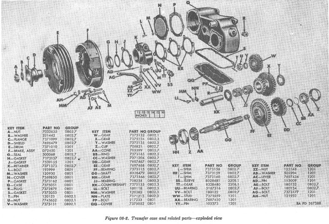
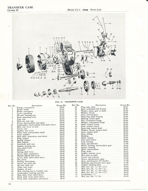
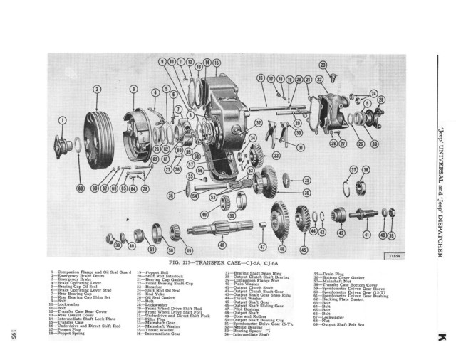
Todays question is about the TFC output oil seals. The civie service manual has a exploded view of the TFC on page 175. The seals marked as #5 and #76 are what I am looking to replace. When I go to my local parts house they show only two seals (front and rear out put shaft) both the same part number. When I read the book it mentions some felt seals and I am guessing those are #76 on the exploded view. Where do I get those seals?
Also I removed the e-brake backing plate and there is no seal visible in the outside of the #7 rear cap. However when looking with a light I can see what looks like the back side of an oil seal on the inside of the #7 rear cap.
Did bubba strike again? Or is the manual wrong?
One last thing, what keeps oil from seeping out around the splines at the companion flange nut?
Oh and this is a 1951 M38 |
|
| Back to top |
|
 |
buzzk
Member

Joined: Dec 03, 2013
Posts: 197
Location: Saint Augustine , Florida
|
| Posted: Sun Dec 28, 2014 8:03 pm Post subject: felt seals |
|
|
| I do believe that the felt seals come with the gasket set for the transfer case buzz |
|
| Back to top |
|
|
Toyvo
Member
Joined: Sep 06, 2014
Posts: 30
|
| Posted: Sun Dec 28, 2014 10:25 pm Post subject: |
|
|
Thanks Buzzk,
I'll check with the parts house and see if they can give me a list of parts in that kit.
Have you ever replaced the TFC output seals? |
|
| Back to top |
|
|
wesk
Site Administrator


Joined: Apr 04, 2005
Posts: 16258
Location: Wisconsin
|
|
| Back to top |
|
|
Toyvo
Member
Joined: Sep 06, 2014
Posts: 30
|
| Posted: Mon Dec 29, 2014 7:56 am Post subject: |
|
|
Wesk !!!! U-DA-MAN !!!
The guide you sent me is exactly what I needed. I was wondering how I was going to lock those shafts in order to torque the nuts and all I need to do is locate the oil seals.
I still don't see how the splines seal against the yoke. But I guess they just do! Some things don't need to be over thought. 
Oh snap! no felt seals I have the new and improved (with slinger) yokes.  |
|
| Back to top |
|
|
Bretto
Member
Joined: Nov 24, 2010
Posts: 1390
Location: Orem, UT
|
| Posted: Mon Dec 29, 2014 8:24 am Post subject: |
|
|
The splines do not seal in the yoke, you have to dab a bit of sealant on them to seal them. I've had luck just adding the sealant just before the last little bit before the yoke is seated. I get the yoke on and just about 1/8" before its fully seated, I take the nut and washer off and add the sealant around the joint then reinstall the washer then nut and torque. This will push sealant into the splines and seal the end of that joint.
_________________
Brett
'51 M38
PHOTO DIARY OF MY BUILD |
|
| Back to top |
|
|
oilleaker1
Member
Joined: May 14, 2009
Posts: 972
Location: South Dakota
|
| Posted: Mon Dec 29, 2014 8:40 am Post subject: |
|
|
| I wash the splines in laquer thinner and then use the spray type gasket cement and spray the yoke from the inside and install it. Works great. After it leaks out past the nut a slings all over, you learn this. LOL, John |
|
| Back to top |
|
|
wesk
Site Administrator
Joined: Apr 04, 2005
Posts: 16258
Location: Wisconsin
|
| Posted: Mon Dec 29, 2014 12:49 pm Post subject: |
|
|
The sealant addition to the splines is listed in the D-18 guide, i have seen it there before.
| Quote: | A35. Install the front output yoke
A35a. Carefully clean the output shaft with brake cleaner.
A35b. Put a small amount of RTV around the base of the threads.
A35c. Lubricate the yoke shaft and slide it onto the output shaft.
A35d. Install the washer and locking nut.
A35e. Torque to 100-120 ft lbs.
A35f. If equipped with a cotter pin install it now.
A36. If equipped with an emergency brake assembly, install it now.
A36a. Install the emergency brake lever on the rear-bearing cap. Torque the nut to 20 ft lbs.
A36b. While positioning the brake lever onto the tensioner spring, slide the emergency brake backing plate onto the rear bearing cap. Note: Make sure to secure the tensioner nut once you have the backing plate installed.
A36c. Install the four bolts and torque to 30 ft lbs. The three bolts that go into the case will need to have non-hardening sealant put on their clean threads.
A36d. Carefully clean the output shaft with brake cleaner.
A36b. Put a small amount of RTV around the base of the threads.
A36c. Lubricate the shaft of the companion flange and slide it onto the output shaft. Note: The companion flange is attached to the rear brake drum, so when you install the flange, you are installing the drum.
A36d. Install the washer and locking nut.
A36e. Torque to 100-120 ft lbs.
A36f. If equipped with a cotter pin install it now. |
He mentions it in A35b & A36b but instead of RTV'ing the entire length of splines he allows for movement between the yoke/companion flange and output shafts splines by only applying it at the base of the threads where the threads stop and the splines begin. Either way will work but his way allows easier removal of the yoke/companion flange later.
_________________
Wes K
45 MB, 51 M38, 54 M37, 66 M101A1, 60 CJ5, 76 DJ5D, 47Bantam T3-C & 5? M100
Mjeeps photo album: http://www.willysmjeeps.com/v2/modules.php?set_albumName=Wes-Knettle&op=modload&name=gallery&file=index&include=view_album.php |
|
| Back to top |
|
|
Toyvo
Member
Joined: Sep 06, 2014
Posts: 30
|
| Posted: Mon Dec 29, 2014 6:03 pm Post subject: |
|
|
Ok that seems to sum it all up. I think i'll use RTV for the splines like Bretto said. Went to the local parts house and ordered a gasket set and brake shoes they should be here tomorrow along with the felt seals for the drive shaft slip yokes. I picked up the good 2 lip seals today and ordered a gallon of TFC oil. All my parts are clean and new u-joints installed on shafts. Boy that thing had some 50 year old grease/clay/rock that was like concrete and had to use a scraper to remove it.
Oh and there was a seal installed at the rear output shaft but it was put in up side down. Bubba strikes again.  |
|
| Back to top |
|
|
Toyvo
Member
Joined: Sep 06, 2014
Posts: 30
|
| Posted: Thu Jan 01, 2015 12:14 pm Post subject: |
|
|
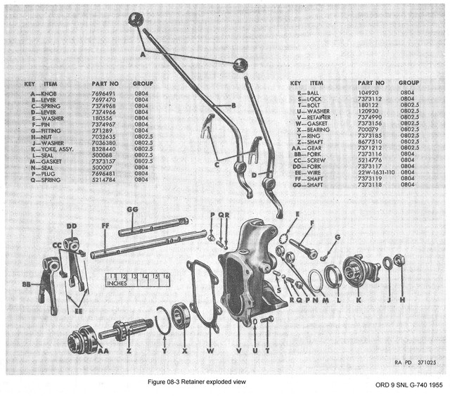
Ok have some parts others coming. On the rear output shaft there was a seal and it wasn't put in backwards. It had a washer installed between the "D" shield and the "G" seal, this washer is not shown on any information I have. I am wondering if my TFC had the felt seals that go between the "D" shield and "G" oil seal and the washer was there so the felt could rub on it and not the "G" seal. So do I discard the washer or order a felt seal?  |
|
| Back to top |
|
|
wesk
Site Administrator
Joined: Apr 04, 2005
Posts: 16258
Location: Wisconsin
|
| Posted: Thu Jan 01, 2015 10:37 pm Post subject: |
|
|
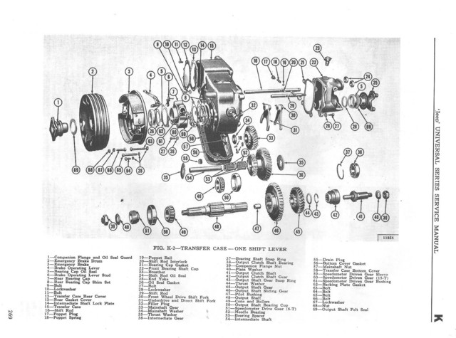
I don't see any reference to your washer. The M38 IPL illustration is above. Here are transfer case illustrations from 6 different service manuals and IPLs and none show your washer. Either someone threw in a part that is not needed or someone tried to address some issue by using that extra part. Are you sure that washer is not a shim that belongs behind the bearing to adjust preload?
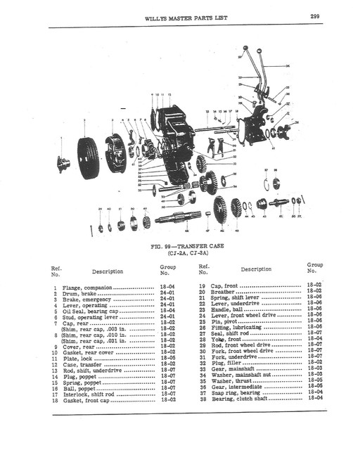
1949 Master IPL for CJ2A & 3A.
1955 CJ5 IPL
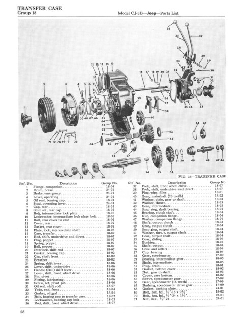
1956 CJ3B IPL
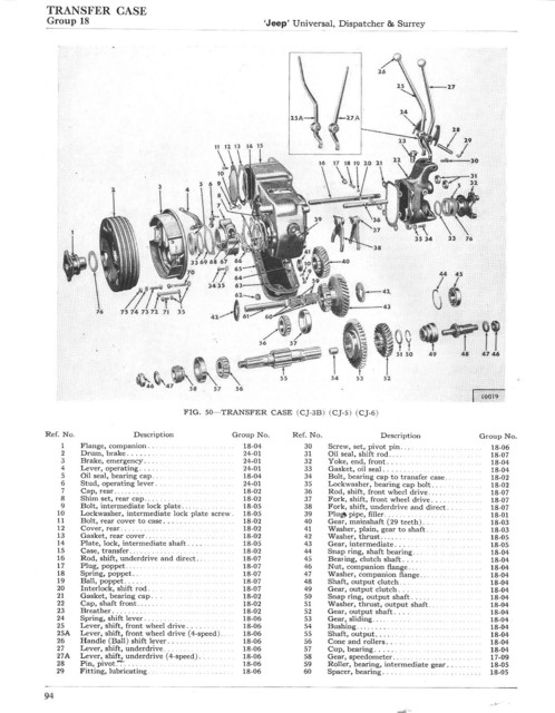
1962 CJ3B, 5 & 6 IPL
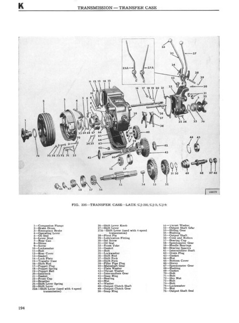 
1965 edition of SM-1002 for CJ3b, 5 & 6
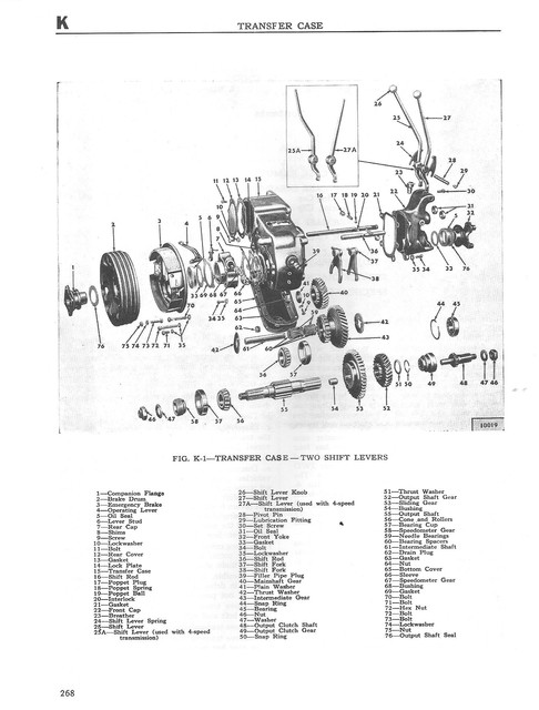 
1971 edition of SM-1046 CJ3B, 5 & 6
_________________
Wes K
45 MB, 51 M38, 54 M37, 66 M101A1, 60 CJ5, 76 DJ5D, 47Bantam T3-C & 5? M100
Mjeeps photo album: http://www.willysmjeeps.com/v2/modules.php?set_albumName=Wes-Knettle&op=modload&name=gallery&file=index&include=view_album.php |
|
| Back to top |
|
|
Toyvo
Member
Joined: Sep 06, 2014
Posts: 30
|
| Posted: Thu Jan 08, 2015 6:59 am Post subject: |
|
|
After some memory search, I have come to the conclusion that the washer use to be part of the original seal. If I am not mistaken the old seals were not stamped from one piece of steal and the rubber stuffed in the middle. They were two pieces of metal and a rubber part that were partly held together by vulcanization. My thinking is that the seal came apart and became two parts, a steel washer and a sleeve with a rubber part in the center.
Thanks for your input Wesk, I know you spent some time looking all that up. |
|
| Back to top |
|
|
Toyvo
Member
Joined: Sep 06, 2014
Posts: 30
|
| Posted: Thu Jan 08, 2015 7:08 am Post subject: |
|
|
Update, I could not fine a supplier for the slip yoke seals (packings) on the drive shafts so I improvised.
Go to your local parts house and order the rear main seal for a 50's Chevrolet engine. This should be a rope seal (tell them you need a rope seal when ordering). Dismantle the slip yoke clean out the old grease and mud. Then cut the seal to fit around the shaft and slip the rope under the cap reassemble the yoke and grease. Works like a champ. |
|
| Back to top |
|
|
|