Joined: Oct 06, 2014 Posts: 252 Location: South Dakota - Aberdeen
Posted: Fri Dec 18, 2015 11:27 am Post subject:
sgtkish wrote:
wesk wrote:
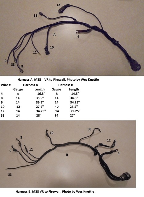
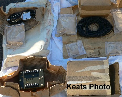
Here's the M38 Harnesses. They are very similar to the A1 harness except for some lengths and the oil press wire does not tie into it.
Wes, I have looked in the parts manual and have come up with a part number of WO-800481. Can you confirm this number correct for the M38 wiring harness that goes to the firewall? Also, what is the difference between harness A and B in your photo? _________________ Aaron
1950 M38 - #MC11328, 24volt, 1948 CJ2A (Lefty)
Page 176, Harness 800481 (Used thru sn 20599) (this serial group change was the result of the switch from the firewall mounted radio ignition noise filter in wire #12 which was discontinued in preference to an internal filter in the distributor.)
Page 171, Cable Assy 804330 (Used from sn 20599 thru sn 65927)(this serial group change was the result of the 3 circuit breakers on the side of the cowl battery box being dropped from production which changed the length of wire #10 after 65927)
Page 171, Cable Assy 806777 (Used after sn 65927)
This is a trick that has been used for many years by the technical writers to fool and confuse the logistic system users. Like the legaleze used in the legal system they rework word meanings to confuse the dickens out of you.
The short version of the last paragraph is: Harness and Cable Assy are one in the same.
The difference between Harness A & B in my illustrations is the individual wire lengths which I have listed in two columns under A or B. _________________ Wes K
45 MB, 51 M38, 54 M37, 66 M101A1, 60 CJ5, 76 DJ5D, 47Bantam T3-C & 5? M100
Using a hand-me-down wiring harness, the VR harness has only one wire (#4) coming out of the plug that is connected to pin A and in the middle of the cable a branch comes out that appear to be the #10 wire. I have an ammeter and one additional CB on the instrument panel. Can #10 be fed through pin A? I guess my question is whether the pins A and C are internally connected inside the solid state VR. Any suggestion is greatly appreciated.
I believe they have an internal connection but the behavior of A & C may not be identical. I would recommend you follow the wiring diagram and connect wire #10 where it belongs. You can try the current arrangement and if it works well then stay with the piggybacked #10. If not then move #10 to pin C. You can also disconnect both plugs from the regulator and check A to C on the 4 pin plug of the regulator for continuity with an ohm meter.
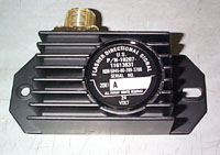
This the only transistorized voltage regulator output diagram I have been able to uncover (top half of photo). It suggests that A, B, C & D are connected internally. _________________ Wes K
45 MB, 51 M38, 54 M37, 66 M101A1, 60 CJ5, 76 DJ5D, 47Bantam T3-C & 5? M100
Sorry to revisit this subject but I'm just about done, and ready to turn over the engine for the first time and ran into some wiring issues. Not only does my brake lights stay on the then go off when pressing the brakes(then flicker for a sec ass peddles down and come back on for some reason) but I only have one blinker ,the front pass working right. The back ones flash dim and together like hassard lights and the green bulb on the switch won't flash at all.
Anyway what I'm getting at is I plugged wire 8and 9 in my, I believe is a volt meter on my m38a1 and turned the power on. The left one wire 8 smoked bad and almost burnt threw the wire. I unplugged it and left wire 9 plugged in the right side of the gauge and turned power on. It works good and shows power in the green side of the gauge without smoke or fire..lol. now you said earlier when using a trans style reg to use wire 27 on the pos of the volt meter. Well my reg is an autolite much and 8 is unplugged and 9 still in the right side, or where wire 9 usually goes I should say. Is this going to work fine , or should I some how make a splitter on on one of the spider wires and plug that #27 in where wire 9 goes on my voltmeter? Or should I get an amp meter and just try to plug 8 and 9 back up to it? Please advise. Thank you
wesk wrote:
The problem with the 60 Amp GI Alternator is it's current price. $300 and up.
If your M37 had the transistorized regulator that doesn't use wire's 8 & 9 you can still use it. You must switch the amp meter out for a voltmeter and just do not use the 8 & 9 wires.
Autolite 28V 25 A mechanical regulator
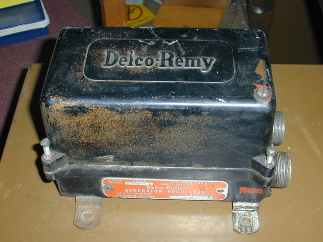
Delco-Remy 28V 25 A mechanical regulator
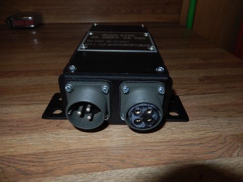
Transistorized 28V 25 A regulator
The plug ends are the same on all three. Up behind the dash wires 8 & 9 connected to the amp meter on the two mechanical regulators. When you used the transistorized regulator you just taped the ends of wires 8 & 9 over and replaced the amp meter with a volt meter and connected the plus side of the volt meter to the wire #27 spider harness.
As I said in the post you quoted, the # 8 & 9 wires are cut off and NOT used with a volt meter. You got the smoked wire because you connected it to the volt meter's ground terminal and if you are using the stock Autolite or Delco mechanical voltage regulator then 8 & 9 are always hot. Do the volt meter add-on as it is suppose to be done. Power it from the #27 spider.
If you do not touch the brake pedal and the brake lites are on continuously you have a stuck switch or you have a brake pressure not completely relieving on pedal release problem. If the brakes lites are off with the pedal up and as you depress the pedal they come on then later go off and then come on again as you continued depressing the pedal you have a bad switch.
The turn signal issue can be more complicated. troubleshooting needs to be done carefully. You first must tell us if you have the early or late military turn signal system or if you are using a standard civilian turn signal switch.
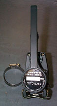
Early military system. The large green relay box is usually on the front of the firewall but sometimes you will find it on the rear of the firewall. The switch fo it is very similar to the civilian switches.
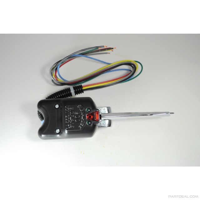
Late military system switch
Late military system flasher box.
Aftermarket civilian switch.
Before you start burning up the clock troubleshooting this issue start with a thorough inspection and cleaning of the inside of all lamp housings and all lamp sockets. Then make sure all the paint is removed from the lamp housing and the body where they come together to insure you have good grounds. Then inspect all wiring looking for side by side wires that have shorted together and anywhere the lite circuit wires have deteriorated insulation. Check each lamp with an OHM meter for continuity. Bad grounds have a nasty habit of causing circuit feed backs that often illuminate multiple lamps dimly at the same time. _________________ Wes K
45 MB, 51 M38, 54 M37, 66 M101A1, 60 CJ5, 76 DJ5D, 47Bantam T3-C & 5? M100
Joined: May 30, 2014 Posts: 3447 Location: Texas Hill Country
Posted: Fri Jan 15, 2016 8:06 am Post subject:
Hello Wes,
Sometime a while back I was looking at various turn signal articles and was able to enlarge the early military signal photos.
I believe the switch is a standard Signal-Stat 800 civvy unit with the green bulb lens out on the end. As you can see the switch is chrome, which suggests a civvy unit, and the instructions say to paint the switch if in combat zones.
The majority of the quality units have an indicator lamp on the switch body. There are published troubleshooting guides for both the early and late military setups and if he has either of the military setups I would advise only using the troubleshooting guides for that system and not downloading a civvy guide and troubleshoot a military system with a civvy guide.
If he has a aftermarket standalone civvy switch system then use that switch's troubleshooting guide. A common issue with the aftermarket civvy switches occurs when the switch gets used in a 24 volt system. Only a very small number of civvy switches offer a switch with a choice of 12 V or 24 V pilot lamps. Usually your on your own to buy the switch, open it up find the pilot lamp and then find a suitable 24V replacement. _________________ Wes K
45 MB, 51 M38, 54 M37, 66 M101A1, 60 CJ5, 76 DJ5D, 47Bantam T3-C & 5? M100
All times are GMT - 6 Hours Goto page Previous1, 2
Page 2 of 2
You cannot post new topics in this forum You cannot reply to topics in this forum You cannot edit your posts in this forum You cannot delete your posts in this forum You cannot vote in polls in this forum