Joined: Nov 01, 2011 Posts: 199 Location: Escondido, CA
Posted: Tue May 22, 2012 3:42 pm Post subject: Re: Electrical questions
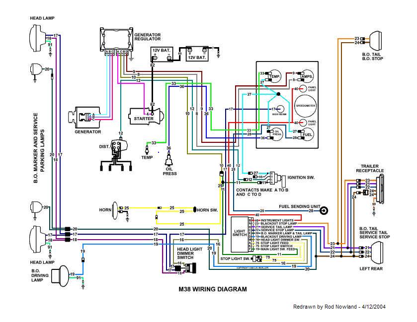
Are you using the colored master wiring diagram late M38 from the downloads section of this site? Here's my interpretation from that diagram:
1. Yes
2. Yes
3. Yes
4. No. There is only one electrical terminal on the starter, shared by the battery cable and wire 4 to the regulator which is the feed for all the electrical system, so everything is "hot" whether the starter is engaged or not.
This is pretty much the same as my '53 Ford pickup except it has a starter button on the dash to a solenoid instead of a foot switch, and, of course, a simpler lighting arrangement.
Bretto wrote:
I have a few question on the wiring/electrical.
1.Does the ignition switch just supply power to the coil, and guages?
2.From what I think I gather looking at schematics, there is always available power to the lightswitch and the horn?
3.Always power available to the starter regardless of ignition switch position?
4.I can't see it, but when the starter is cranked, is it set up to kill the power to everything so all amps are directed to the starter?
Thanks,
Brett
_________________ Jim McKim
1952 M38 son-father project
Slowly turning rusty parts into OD parts
Joined: Nov 24, 2010 Posts: 1390 Location: Orem, UT
Posted: Tue May 22, 2012 10:19 pm Post subject:
Putting aside the specific M38's schematic, is specific ammeter placement critical as long as you place the regulator's output to it and the other side to the battery? Reason I ask is I have seen some diagrams where the horn is on the battery side of the ammeter. The m38's looks like everything is on the output side of the regulator. Just what does the ammeter read, is it just the charging amps? _________________ Brett
'51 M38
PHOTO DIARY OF MY BUILD
What circuits are on which side of an amp meter are important when you have a direct reading amp meter (one that lies directly in the path of the current flow) like the WWII MB.
The M38 amp meter is a shunt type amp meter. That means it gets it's current flow info from a shunt that is placed directly in the path of the current flow. The shunt is connected between pins A & B of the voltage regulators firewall connector. A is wire #4 that runs to the battery and B is wire #8 that runs to the amp meter. The shunt senses this load amount and direction and sends the info in the form of a voltage signal thru wires #8 & #9 to the amp meter.Pin C is wire #10 which is all loads except the starter.
The horn you mention that you see often on the battery side of the amp meter in other vehicles is an intermittent load and is not normally needed to read to determine rate of charge. _________________ Wes K
45 MB, 51 M38, 54 M37, 66 M101A1, 60 CJ5, 76 DJ5D, 47Bantam T3-C & 5? M100
Joined: Nov 24, 2010 Posts: 1390 Location: Orem, UT
Posted: Wed May 23, 2012 7:57 am Post subject:
Thanks Wes.
Makes sense about the horn.
Im just trying to map out my wiring on this project. I'm having to run this as a 12V set up so Im utilizing the schematic of the M38 and just redrawing it with the equipment I have. The M38 originally came to me with 12V set up and was runing as such. There are just a few items I'm changing in order for it to look and function like stock. Mainly adding a stock ignition switch, a foot starter switch and will attempt to modify the 3 lever lightswitch to work with 12V.
-Brett _________________ Brett
'51 M38
PHOTO DIARY OF MY BUILD
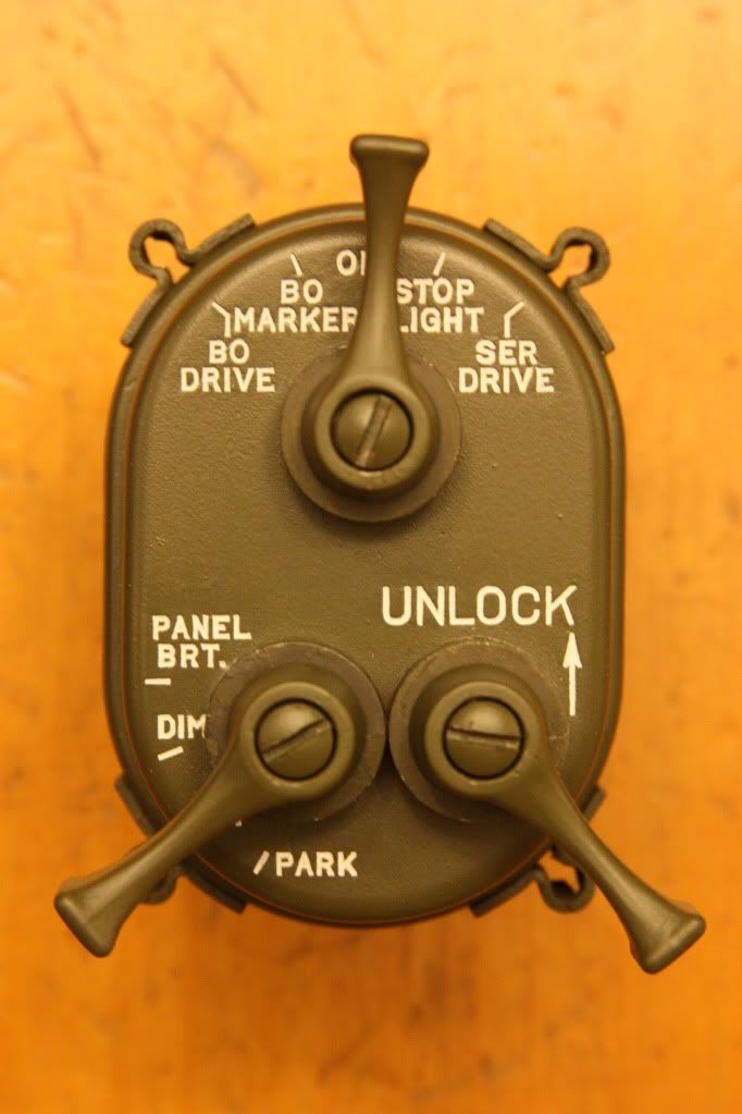
The 3 lever lightswitch will be a problem. The more common late switches have a built in circuit breaker. Since 24 volt components use much less amperage than like 12 volt components the switch to 12 volt will mean an increase in amperage loads passing through the circuit breaker. We are fortunate the military insisted on much heavier wiring then was needed for 24 volt systems thus we can safely run 12 volt components on the military wiring. But the 24 volt circuit breaker could start giving you nuisance trips. I would suggest you find one of the earlier Bendix/Scintilla brand switches that will have two advantages. One they do not have a built in circuit breaker and two they are easily rebuilt and repaired. Then just add an appropriate size 12 volt rated fuse or circuit breaker in the #11 wire. If you have the early M38 with three circuit breakers on the inboard side of the cowl battery box then replace those circuit breakers with the correct 12 volt amperage ratings.
The left or center switch are the Bendix/Scintilla switches.
Early switch front view.
Switch external wiring is the same. This is a late switch and you can see the only difference in the internal wiring is the addition of the circuit breaker just to the right of the H & N pins. _________________ Wes K
45 MB, 51 M38, 54 M37, 66 M101A1, 60 CJ5, 76 DJ5D, 47Bantam T3-C & 5? M100
Joined: Nov 24, 2010 Posts: 1390 Location: Orem, UT
Posted: Wed May 23, 2012 9:13 am Post subject:
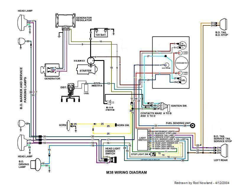
This is what I have so far. I omitted the oil and temp, mine are mechanical. Also I put the floor switch going thru the dash switch so it will be disabled when off. Does anyone see any problems with this? Critisism welcomed.
Ya I beleive I have a late model switch. Are they hard to break into by bending open the crimps tabs? I was thinking that would be the way to go and bypass the breaker and add an appropriate rated fuse externally.
Maybe someone would trade me, mine looks real pretty right now _________________ Brett
'51 M38
PHOTO DIARY OF MY BUILD
The late switches were not designed to be serviceable. They were meant to be throwaway's.
You should use a photo editing program and work at making changes to the original color M38 diagram as you go.
If you switched to a civvy 12 volt starter that uses and external solenoid then you should have no problem wiring the light duty side of the solenoid to your ignition switch. _________________ Wes K
45 MB, 51 M38, 54 M37, 66 M101A1, 60 CJ5, 76 DJ5D, 47Bantam T3-C & 5? M100
Joined: Nov 24, 2010 Posts: 1390 Location: Orem, UT
Posted: Wed May 23, 2012 9:23 am Post subject:
Yep my 12v starter has an external solenoid. The above wiring diagram is my redo of the original and my proposed layout. _________________ Brett
'51 M38
PHOTO DIARY OF MY BUILD
Joined: Nov 24, 2010 Posts: 1390 Location: Orem, UT
Posted: Wed May 23, 2012 6:49 pm Post subject:
Any feedback on the redesigned circuit? Nothing is different on the lighting circuits. Major changes are on the ignition and the charging circuits.
Thanks,
Brett _________________ Brett
'51 M38
PHOTO DIARY OF MY BUILD
Joined: Nov 24, 2010 Posts: 1390 Location: Orem, UT
Posted: Wed May 23, 2012 10:26 pm Post subject:
#10 wire is just going to the one terminal (batt) on the regulator same with #8
The regulator terminals read left to right GFAB and are your basic ground G, field F, armature A and batt B and they terminate to the genny of the same labeling.
Regulator is a bosch 12h104.
The wiring, when placed, will sized accordingly and fused protected.
About the ammeter, I may not know what you mean. If you mean does it not have a parallel shunt resistor, it will. _________________ Brett
'51 M38
PHOTO DIARY OF MY BUILD
Joined: Nov 01, 2011 Posts: 199 Location: Escondido, CA
Posted: Thu May 24, 2012 1:09 am Post subject:
Looks good to me.
An ammeter is actually a voltmeter measuring the voltage drop across a resistor, or "shunt", with a scale marked in amps instead of volts. It works on the principle of Ohm's Law that voltage across a resistor is proportional to current through the resistor. The shunt carries the majority of the current. Whether the shunt is internal or external is simply a matter of construction. A direct reading ammeter has an internal shunt and can be put into any DC circuit up to its rating and doesn't depend on being connected across a particular external device as in the original M38 system. _________________ Jim McKim
1952 M38 son-father project
Slowly turning rusty parts into OD parts
You cannot post new topics in this forum You cannot reply to topics in this forum You cannot edit your posts in this forum You cannot delete your posts in this forum You cannot vote in polls in this forum