Posted: Tue May 06, 2014 7:59 pm Post subject: Ignition Wiring and more
So I attempted over the weekend to get the engine going from the '51 M38 that I just brought home, but could only get the starter to turn. (yes, I did put new points, condenser, rotor etc)
I checked with a Multimeter and learned that I didn't have power going to the ignition coil. After further inspection I realized that the wires are in pretty "sorry" shape:
What you see in these pictures are the wire going to the ignition coil, its "sad" connection to the wire going to the ignition switch and the porr connection at the ignition switch itself. One picture of the circuit breakers as well.
I studied the ignition wiring diagram for quite some time today and concluded that the power goes directly to the starter from the battery and the starter did measure 24 volts. From there it goes into the regulator and out of the regulator, to the circuit breaker and then to the ignition.
So how do I test if I have power going to the regulator? Or should I?
More importantly I asked myself: Why am I doing this? For now I am just trying to get the engine going. Couldn't I use some short cuts and make up some wiring and do that? Something like: Ignition to distributor and ignition to battery and battery to starter?
It sure looks like I need to replace my complete wiring harness and unless I am wrong I can't buy just sections at a time and I can't afford to buy a whole new harness right now, plus it probably isn't the right time in my restoration to do that anyway.
It's not time to do a $750 harness change. Don't overthink your work around.
Disable/Disconnect all circuits not needed. They are:
Electric instruments.
Lighting.
Horn.
If you are grasping what I've said so far you will know that only leaves the starter and the ignition. Start by disconnecting the battery ground cable.
The easiest way to loose the unnecessary circuits is to disconnect the #4 wire from the starter terminal. Now the only components with juice are the two batteries and the starter.
Sounds simple doesn't it? Well the Army wasn't to dumb with there tactical vehicle specs in 1948.
Now get a 15 amp fuse and inline holder and some new 14 gauge wire and two 20 amp rated toggle switches and a small mount plate for them you can bolt to the bottom of the dash. Mount the two switches to the dash. Label then Master and ignition.
You will need some basic instruments for the jeep during this test period.
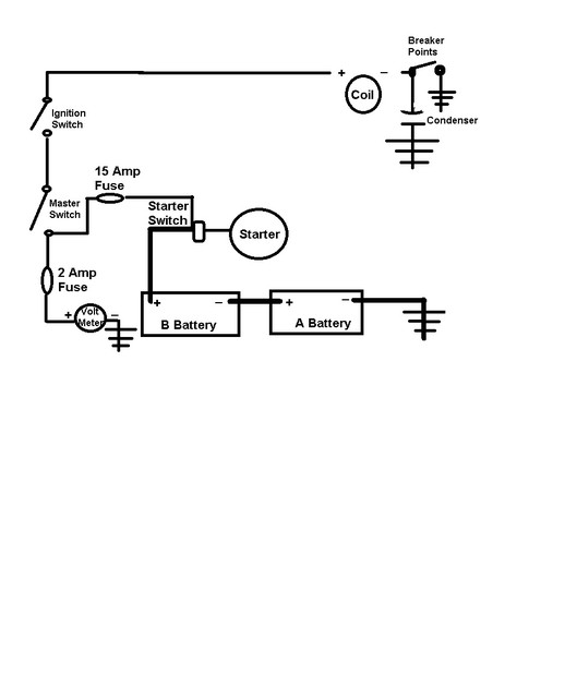
Buy a cheap set of mechanical gauges (oil press, water temp) and a voltmeter. Connect the oil pressure gauge to the tapped hole in the block where the electric sender was. Connect the water temp gauge to the tapped hole in the head where the electric sender was. Connect the + lead from the voltmeter to the output of the master switch. If you wish place a 2 amp inline fuse in the voltmeter circuit. Connect a wire between the input of the ignition switch and the output of the master switch. Connect the voltmeter - (ground) wire to the tub. Now connect one end of the inline 15 amp fuse holder to the input of the master switch. Then connect the other end of the 15 amp fuse holder to the same starter terminal you removed Wire #4 from. Now run a new wire from the ignition switch output to the distributor.
For the distributor connection you should remove all the bad wires inside the distributor and install new wires. Do not bother with the radio noise filter inside the external electrical plug. Just remove the noise filter and run the new ignition wire from the ignition switch directly to the coil's + terminal. Now with a new internal ground wire to the points and a new condenser and points you should be ready to test the circuits.
The distributor internals that you may want to work on are in this photo:
Wire "a" comes from your new ignition switch. Wire "B" goes from the coil to the points and then to ground. That shiny thing at the top of the photo is called a condenser. You should get a new one. Looking at your photos it looks like someone has already deleted the radio noise filter capacitor that was inside that small square fixture with the four screws. For now just unscrew that and leave it off. Take the new temporary ignition wire and feed it through that hole and connect it directly to the + terminal on the coil. _________________ Wes K
45 MB, 51 M38, 54 M37, 66 M101A1, 60 CJ5, 76 DJ5D, 47Bantam T3-C & 5? M100
Per my original post- I did in fact already install a new condenser, points and rotor.
I think I grasp everything else you are suggesting, but will read about 20 more times to be sure
I want to make sure we are on the same page though: All I am trying to do is temporarily see if the basic engine functions are there. Think of it as the engine being completely removed from the Jeep.
The fine tuning will have to happen after I add the correct carb, fuel pump and make sure everything else works. Does that make any sense?
I want to make sure the basic necessities are going to the engine, that being fuel and electricity to see if it will run. Are the fuses and gauges etc really necessary for this?
Based on the diagram you provided wouldn't I be able to achieve what I am trying to do by simply connecting the ignition switch to the coil and the starter switch? And the battery to the starter?
I have all of the gauges that came with the Jeep.
The tub is coming off and I already disconnected just about everything else.
The presentation above allows you to operate the engine only and operate it safely. It eliminates all other electrical circuit distractions. I can see from what you have done so far that the engine will not cooperate right away and start right up. This long term use of the temporary wiring makes it important to protect the circuits. Everything you do here is excellent training for what's to come. The first time you fire up a new to you old engine you must have accurate temp and oil pressure readings. In the future when you troubleshoot engine oil pressure and temp problems you will again have to ditch the military electric gauges and use direct mechanical gauges to insure that you know what press and temps you really have. When troubleshooting the military instruments you will need to substitute these same two mechanical gauges so why not get them right now?
That wiring set-up I posted for you is very simple, cheap (less than $30). You can buy a cheap pair of mechanical oil press/water temp gauges with a mount that goes under the dash for $20.
Using these will allow you to get the engine running and run it long enough and often enough to evaluate the engines true condition and even the condition of the running gear. When you have the chassis, tub and running gear restored and back together your next step is to install the restored engine and again you have the perfect simple set-up to test run the engine before you get the fenders and hood on. Even before you buy or fabricate the new harness.
Quote:
Based on the diagram you provided wouldn't I be able to achieve what I am trying to do by simply connecting the ignition switch to the coil and the starter switch? And the battery to the starter?
That is what I did. The only thing different from what you wish to do is the voltmeter and the two fuses. The beauty of my installation is it will function safely for years and you can even test the generator/regulator by simply touching the old wire #4 to the starter switch terminal and watching your new volt meter. _________________ Wes K
45 MB, 51 M38, 54 M37, 66 M101A1, 60 CJ5, 76 DJ5D, 47Bantam T3-C & 5? M100
You cannot post new topics in this forum You cannot reply to topics in this forum You cannot edit your posts in this forum You cannot delete your posts in this forum You cannot vote in polls in this forum