This thread is in Draft form; subject to examination, corrections and additions by people who know a lot more than me.

Wes gave us the VBC Regulator & Relay Prestolite Service Info Sheet (above), which also appears in a NGBB from 1967 (below), but not in the exact same wording.
Wes also pointed out a Rosetta Stone clue that lets us pick info that pertains to my VBC-4004UT target subject.
Not all VBS-4004UT VR's are the same.
"That 3Z serial puts your regulatory as listed on page 2 of the Prestolite spec sheet in the 12X to 6Y group."Wes.
Without that nugget our research data here and to come would be tainted.
I have tried to combine info from the two sources and present it in an easier to manipulate text format. Please evaluate my efforts and point out any errors, misleading typos and omissions. Thanks, Don
****************************************
From National Guard Bureau Bulletin. Vol. 18. No. 20 67
VOL. XVIII , NO. 20 , 67 3 . TRUCK , 1/4 TON , M151, M151A1.
Several States have reported difficulty with the Voltage Regulators on the subject series vehicle . As an interim measure , the following tentative Prestolite service manual specifications may be used as guidance in checking out and adjusting the vehicle voltage regulators .
VOLTS 24
GROUND POLARITY Negative
RESISTORS See tabulation ( R1-4?)
CONDENSER CAPACITY 2.0 to 2.7 Microfarads
CIRCUIT BREAKER
Resistance of Voltage Winding 214.7 to 237.3 Ohms
Armature Core Gap .066 " to .070 "
Contact Point Gap .047 " Minimum
Contacts Close 25.0 to 27.0 Volts
Contacts Open
5.0-10.0 amp discharge at 25v after charge of 10 amp min.(My 4004UT only)
VOLTAGE REGULATOR
Resistance of Winding 154.8 to 171.2 Ohms.
Armature Core Gap
.057" to .060" (My VBC-4004UT only. Code Dated 12X or later)
Contacts should be closed with the high limit gauge in place on the contact side and next to the armature stop pin .
Pressure of Contact Points
7-8 ounces except VBC-4004UT
(So what is the value for my VBC-4004UT ?)
Gap Between Contact Spring and Armature Stop
.010 " to .016 " Except VBC- 4004UT
(So what is the valve for my VBC-4004UT ?)
Clean contacts using number 6 Swiss file, then clean with paper.
Operating Amps 25.0 +/- 2.5 Amps
Operating Voltages
Figures for a unit in normal operation while charging at 1/2 maximum output. Use Test B for my VBC-4004UT : (28 +/- 1.0 volts)
28.0V @ 50deg. / 27.85V @80deg. / 27.6V @110deg. / 27.3V @ 140deg.
Tolerance = +/- .5 Volts
VBC-4004UT (Units 12X- 6Y)
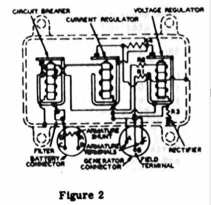
Test/B R1/575 R2/60 R3/40 R4/200 Fig.2 (R= Resistor #)
CURRENT REGULATOR
Armature Core Gap
.057 " to .060 " (My VBC-4004UT Unit 12X & Later)
Contacts should be closed with high limit gauge in place and open with the low limit gauge in place on the contact side and next to the armature stop .
*Notes #1-3 apply only to VBC-4004UT before 12X... not mine. (I think)
*Notes from NGBB and Prestolite Service Info Sheet are not the same.
*Note #4 may apply to all units (I think)
NOTE 1 (From NGBB) - (May not apply to my VR unit.)
On voltage regulator , temporarily remove spring and loosen stationary contact and check float of the armature . Bend each hinge ear to establish an .052" to .056 " core gap . Reassemble spring and adjust stationary contact to provide an armature core gap of .052 " to .056 " . Mount the regulator in the same position as it will be used on the vehicle . Do not connect the battery to the regulator . Start the generator and increase the speed to 5000 rpm. Ad just the voltage to 28.0 + .2 volt . Voltmeter needle should not fluctuate more than + 0.5 volts from the set value . If fluctuation is more than this , stop the generator and clean or replace contacts . Connect a battery and operate for 20 minutes at 12 to 13 amperes load . Stop the generator , remove the load and restart the generator , increasing speed to When a 0 to 4 ampere charge to the battery is reached , stop and restart the generator five times . The voltage should be within 0.5 volt from the set value with 12 to 13 amperes load . 5000 rpm. NOTE 2 Adjust circuit breaker by inserting correct size wire gauge between armature air gap and core on contact side and next to brass pin in core . Gap should be .066 to .070 inch . Ad just gap by bending armature stop
NOTE 1 (From Prestolite Service Info Sheet) - To be added later.
NOTE 2 (From NGBB) (May not apply to my VR unit.)
Adjust circuit breaker by inserting correct size wire gauge between armature air gap and core on contact side and next to brass pin in core . Gap should be .066 to .070 inch . Ad just gap by bending armature stop .
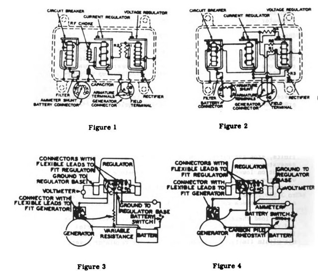
Mount regulator on test stand in same position that it is mounted on vehicle . If this position is unknown , mount with base vertical and terminals pointing down . Use GHA generator and mount on test stand . Connect battery for 24 volts and negative polarity . Connect regulator , generator , battery and meters . (Figure 3 ) Polarize generator to prevent burning regulator contacts . Το polarize , first remove generator field lead from variable resistance then close test stand battery switch and touch field lead to regulator battery terminal for not longer than one second . Connect field lead to variable resistance Adjust variable resistance to insert all resistance in field circuit . Start generator and operate at 1,000 to 2,000 rpm . Decrease field resistance until ammeter shows a charge of one half current value stamped on regulator name - plate . Now increase resistance slowly. Note amperage discharge just before contacts open and ammeter reading drops to zero . Adjust closing voltage to 25.7-26.7 by turning adjusting nut on lower end of armature spring . Check closing voltage after each adjustment . Ad just opening discharge current to 7.0-11.0 by raising or lowering stationary contacts . Open test stand battery switch to prevent shorting . Bend stationary contact bracket to increase or decrease gap . Increasing contact gap increases opening discharge amperes . Keep contacts aligned for full face contact and adjust both sets of contacts so they operate simultaneously . Do not adjust gap between contacts to less than 0.025 inches . Open test stand battery switch
NOTE 2 (From Prestolite Service Info Sheet) - To be added later.
NOTE 3 (From NGBB) (May not apply to my VR unit.)
Adjust current regulator by changing connections to those shown for voltage and current limiter test as shown in Figure 4 . The load rheostat may consist of a carbon pile or lamp bank .
On units that have been completely repaired , close test stand battery switch and operate generator at 2,500 to 3,000 rpm . Test current limiter by pressing lightly on back of voltage limiter armature to hold contacts closed . Read ammeter . If reading is 24.5-26 , do not ad just . If current setting is within two amperes , turn adjusting nut on lower end of armature spring . Release voltage limiter arma ture. To test voltage limiter , stop generator , then start and bring speed up to 2,500 to 3,000 rpm . Ad just current to one- half the value stamped on the regulator name- plate by changing carbon pile rheostat or lamp bank . Read voltmeter . If reading is within 0.4 volt of correct operating voltage , do not adjust . If voltage is not within 0.4 volt of specific voltage ( Page 4 ) , turn adjusting nut on lower end of arma ture spring . Stop generator and open test stand battery switch .
Install cover gasket and cover on regulator. .. close test stand battery switch and operate generator at 2,500 to 3,000 rpm . Adjust load rheostat or lamp bank so ammeter reads one-half current regulator operating amperage . Operate at this current for 30 minutes to bring regulator up to operating temperatures .
Place thermometer near regulator to ascertain air temp around unit . Thermometer must not touch regulator. Stop generator , then immediately start and bring it up to 2,500 to 3,000 rpm. Ad just current to one- half current limiter operating current ( Page 4) . Read voltmeter and thermometer . Voltage must be within limits specified for voltage regulator for temperature specified ( Page 4) . If voltage is not within limits , stop generator , open test stand battery switch and remove generator cover . close switch and start generator . Turn adjust ing nut on lower end of voltage limiter arma ture spring until voltmeter reading is within limits . Check this setting by first stopping generator , then operating generator at 2,500 to ad just and check voltage limiter if not within operating limits .
and read ammeter . Reading must be within limits specified for current limit operating amperage ( Page 4 ) . If current is not within limits, stop generator and remove regulator cover . Start generator and adjust current setting by turning adjusting nut on lower end of armature spring .
Stop generator and open battery switch . Secure all screws on regulator and tighten lock nuts . Install regulator " O " ring and cover . close test stand battery switch and operate generator at one half current regulator setting for five minutes . Check voltage and current setting as above . Make any necessary adjustments and finish with final five minute run and check to be sure generator regulator is now in operating condition and ready for sealing .
NOTE 3 (From Prestolite Service Info Sheet) To be added later.
Note 4 Found only on Prestolite Info Sheet. (I think.)
When (2) nuts are provided on adjusting screws, the upper nut is for locking and should be tightened after each adjustment.
Only Fig. #2 below goes with VBC-4004UT (I think.)