When it came time to tackle the brakes, I had to weigh my options:
1) Rebuild the factory 9" brakes
2) Upgrade to 11" drums in the front from a CJ5
3) Upgrade to front discs with a GM caliper adapter
When I researched these upgrades to improve braking performance, I found that the amount of work involved in an 11" drum conversion is #@$%@ near just as much work as doing the disc conversion. If I were going through that much time and effort, I would rather have the disc brakes in the front for the additional stopping power. The only advantage to the 11" drums is that the discs require wheel spacers in order for the calipers to clear the wheels. After pricing out all 3 options, and after a lot of hours of researching on the computer, I decided I would stick with rebuilding the 9" drums. I'm building an old Jeep, and it's going to drive like an old Jeep. From my time researching, I feel confident that with a factory powerplant and properly adjusted 9" drums, I should be able to safely drive my Jeep around town while remembering that I am, in fact, driving an old Jeep without power steering and 4 corner drums that require some additional stopping distance.
First step is replacing the brake drums as all 4 of mine were already cut to the max size of 9.060". Replacement OEM brake drums are $60 each from Kaiser Willys or Walcks 4WD, however, a thread on this site by Brad (Southpw) had found that the Raybestos 2300R brake drum from a 1959-1969 CJ5 had the same specifications as an M38:
http://www.willysmjeeps.com/v2/modules. ... ic&t=10815
Brad's original screenshot from
September 17th, 2016, shows a Nomimal diameter of 9.00" and a Discard diameter of 9.06", which means they would be the perfect diameters for replacing my M38 drums. However, once I found the drums on Raybestos website, and current as of the writing this post
January 18th, 2021, these drums are specified to have a Nominal diameter of 9.06". The Raybestos website now shows the dimension listed as MM and the metric equivalent as IN, and although the units are inadvertently swapped, the numbers are correct.
https://www.brakepartsinc.com/raybestos ... hange.html
Finding these drums on Rockauto was easy enough searching by part number 2300R, and after shipping, all four drums were delivered for just under $100.

Taken before painting, after drilling the countersinks deeper for the hold down screws, and after degreasing.
Now that I had the drums in my hands, I measured their
Inside
Diameter, and they did infact match the current specs on Raybestos' website. With an ID of 9.060" this meant I would need to do either one of two things:
1) Shim the factory thickness liners out to match the ID of the drums, or
2) Install oversize thickness liners on the brake shoes to match the ID.
If you read my posts in Brad's thread about the drums, you'd see that I called a shop that previously used to install oversize thickness liners, however, they no longer do the shoes themselves in-house. Rather than paying for a middle-man, and after not being able to find any other shops that installed oversize thickness liners, I ventured off to the internet to find another option. Eventually I had found a walkthough on how to make my own liners from scratch, and as much as I would like to give the creator credit for their excellent knowledge, pictures, and descriptions, they did not put their name on the walkthrough anywhere. I will use my own pictures and describe my work to the best of my ability, just know that this process is not my own, and that the credit goes to the creator of that original walkthrough I found online.
Making new shoe liners started with ordering a 6 foot length of 2" wide, .250" thick brake lining material from McMaster Carr. If you follow the TM 9-8012 specs for the factory thickness of the brake shoes, you would see that they were 7/32" thick, which means that by using 1/4" thick liners, I would be adding 1/32" per shoe, for a total of 1/16" additional diameter across both shoes, matching my new drum ID of 9.060" perfectly. Also by following the TM for the length of the liners, I calculated that I would need just under 6 feet total of liner. I did not buy extra. While researching brake liner materials, I decided to use a non-metallic liner. Although my research suggested that the semi-metallic liners might last longer, they are made with an integral woven brass mesh that reportedly causes the liners to run hotter. At the expense of longevity and possibly requiring more frequent shoe adjustments, I elected the non-metallic liners for cooler brake liner temps that would hopefully reduce braking fade. At the additional cost of possibly adjusting the shoes every 500 miles, this will likely be once per year in the Spring time before a driving season starts. In order to help possibly visualize any rapid deterioration in brake liners, I chose to paint the drums with a very reflective, vibrant chrome colored high temperature paint.

I'm terrible at remembering to take pictures, and it is just now that I realize the only picture I have of the drums painted is as they sit on top of the empty dog food bag I used to keep the snow off them

.
When ordering the brake lining material, I also ordered the 5/32" diameter rivets I would use to hold the lining material to the shoes. By using copper rivets with brass mandrels, my hopes are that if the liner ever wears down to the rivets, the softer metals will minimize any damage done to the drum ID. I ordered the rivets from Hansen Rivet Company in California, whose excellent customer service I could not speak more highly of. The rivets I used have a gripping length of .126"-.187".
I got to work on cleaning up the old shoes. Five out of eight shoes say Bendix, the other 3 are unbranded. The old liners were held on with adhesive and required extensive chiselling to remove.

One of the unbranded shoes did not have any holes, so after following the template of another shoe, the new holes were laid out and drilled.
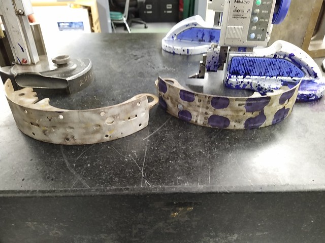
You can see a faint scribe line for the location of the holes on the right shoe. Excuse the blue layout fluid explosion that previously occured on the height stands, that stuff sticks to everything...
After all the old adhesive was removed, the shoes needed to be media blasted clean.

Once the shoes were cleaned, they received a nice coat of high-temperature flat black paint, which I never photographed

.
With the drums on standby to check fitment, the rivets and brake lining material in hand, and the shoes dry, they were ready for their new liners.

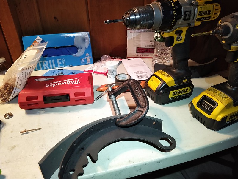
I started at one end of each shoe using a C-clamp to hold the liner in place. From the inside of the shoe, I pilot drilled the hole for the rivet body through the lining material. Moving to the wear face of the liner, I counterbored the rivet hole.

Using electrical tape wrapped around the body of the counterbore bit as a depth marker, this picture shows how deep the rivet heads are from the liner face. I approximated around .100" of the liner is below the rivet head.

The counterbore bit at depth.
Inserting the rivet through the liner, you will see that since the rivet head is below the face of the liner, a standard pop rivet tool will not be able to apply pressure against the rivet face. On the lathe, I turned a small toolsteel adapter with a diameter that protrudes into the liner and allows a larger face to contact the rivet tool.

The smaller diameter on the right end of the adapter fits into the counterbore of the liner and pushes against the rivet face. The small diameter on the left side was a test diameter that I turned off in the next picture.

The adapter fully seated on the rivet face. This allows the rivet tool to press against the larger face of the adapter and not against the liner.
After finishing both rivets on the end of the shoe, I moved the C-clamp down to the next set of holes. By using the C-clamp to slightly squeeze the liner next to the hole I was drilling, when the rivet was installed and the clamp removed, the liner would retract back and the end result was a very nice tight fit between liner and shoe.

No gaps, no need for adhesive.

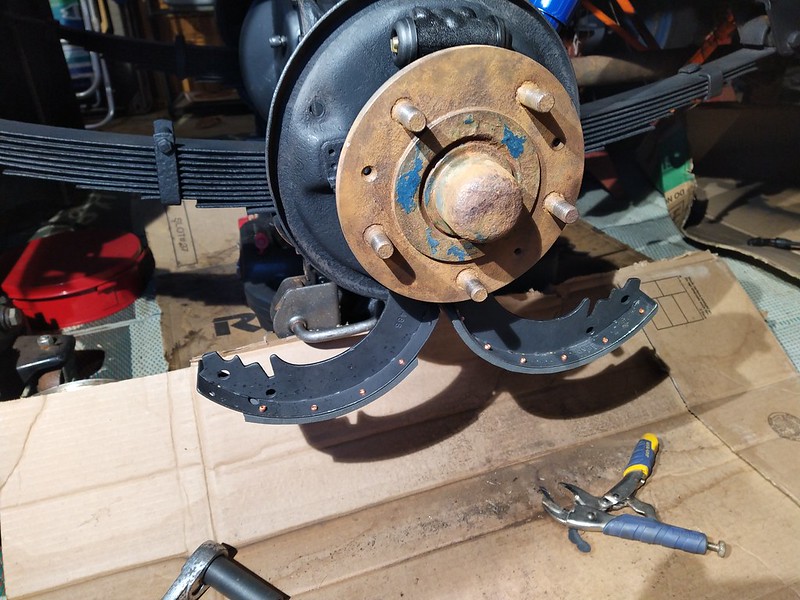
A finished shoe. I added small bevels on the ends of the liner so that there would not be a sharp transition onto the liner face.
After a few beverages and more hours than I care to admit, I had completed four long shoes and four short.

Back out to the garage with the shoes, I found it easiest to align the pivot pins through the plate, slide the cam washers onto the pivot pins, then hold the shoes onto the cams, all with one hand.

Then, I guided both pivot pins through the holes in the backing plate and installed the lock nuts and washes on the backside with my free hand. It was a bit of a juggling act, but by the time I got to the fourth corner, I was getting "good" at juggling.

Holding the pivot pins in place with my right hand so that I could reach in back and install the lock washers and nuts.
At some point in my time on the computer, I read a post where someone mentioned how their brass cam washers were not as thick as their shoes, and that when they tightened down the nuts for the pivot pins, their shoes would not move. So at each corner during assembly, the first thing I did was fully tighten each nut on the pivot pins to make sure the shoes could move freely.

In this picture, the pivot pin nuts are fully tightened, and as you can see, the shoes are both caught to the point where although I can force them to swing up, they are not moving freely. I forced the shoes up and down a few times to see where the paint would be scratched off, and then disassembled.

Here you can see where the shoe, not the the brass cam washer, was what was being tightened down onto between the pivot pin plate and the backing plate. After polishing the shoe with the sanding drum on the Dremel tool, I cleaned up the faces so that they would not contact the pivot pin plate or the backing plate.
Upon reassembly, you can see that the shoes now dropped down freely on both sides and then could easily swing up to meet the wheel cylinder.
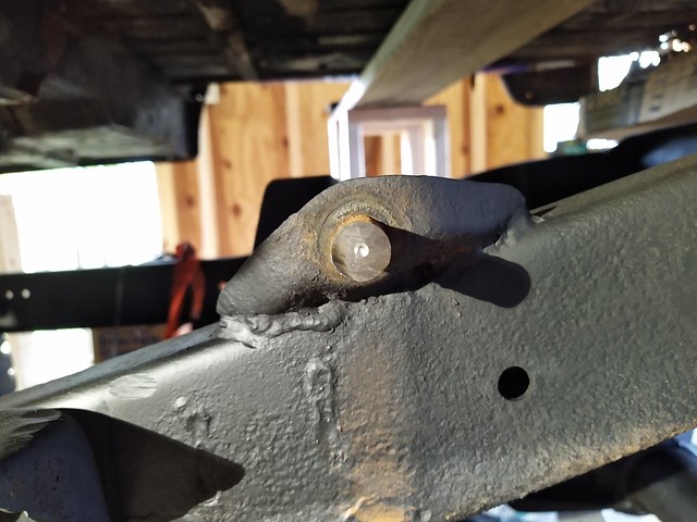
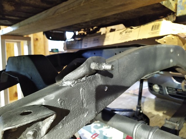
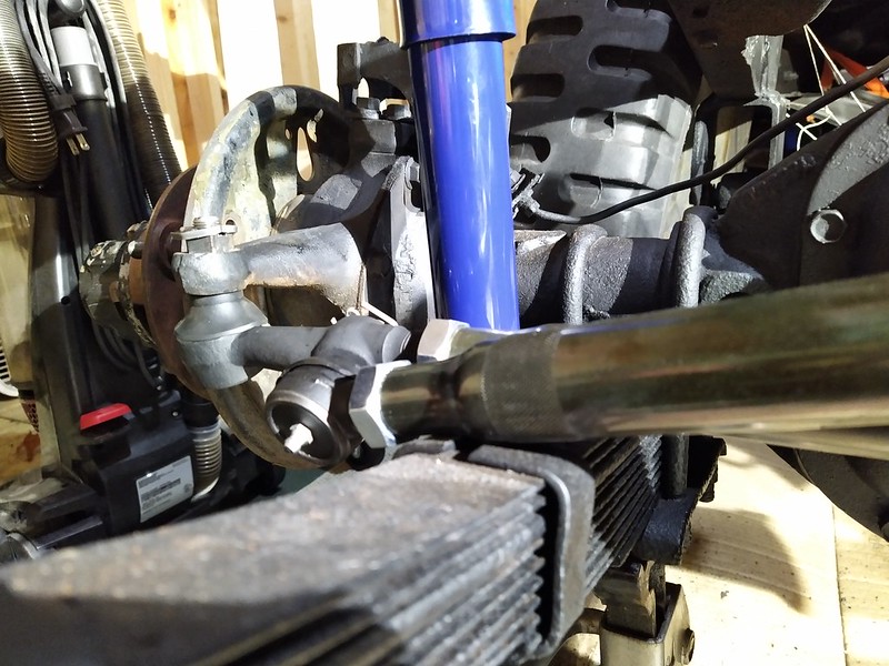
With the rear assembled, I moved to the front.

And after all four corners were assembled, I installed the drums, which I forgot to take pictures of, and then adjusted the brakes to a slight drag, which I also did not photograph. Now the brakes are ready for a light run-in and future adjustment.