Joined: May 30, 2014 Posts: 3447 Location: Texas Hill Country
Posted: Sun Jan 30, 2022 9:34 am Post subject:
Its not impossible to remove the bezels. Putting it back on is the PITA, but it can be done.
Trick would be removing and reinstalling the needle. The face screws on if I remember correctly.
Swap the face on one with the working body of the other?
Id sure try that before sinking 100 simoleons or more for a rebuild, unless you want a factory unit.
Since the one is damaged, practice removing the bezel on that one. Just remember, metal, once stretched past the elasticity point wont come back. A little bit goes a long ways.
Joined: Aug 31, 2010 Posts: 1741 Location: SO IDAHO
Posted: Sun Jan 30, 2022 10:56 am Post subject:
unlike my 3A or any other early jeeps the M38 gage cluster is so easy to deal with as far as swapping components goes. Heck after rebuild I drove mine with a oe non-op AC speedo for 2 years before a good one came along, until then I licked my thumb, held it in the propwash and knew I was within 2.5mph of actual.
Don you're highly motivated and looking for results while waiting for other components to come back from machine, paint etc. Looking at a ready to drop in instrument cluster sitting on the finished parts shelf would certainly be satisfying. Point is gage swaps are easy and good takeout parts become available (usually after you have dropped a few Benjamins on a NOS purchase). _________________ keep 'em rollin'
RICKG MC 51986 DOD 01-52, '50 CJ3a
Rick...... good plan.
Brian. You are walking around in my head.
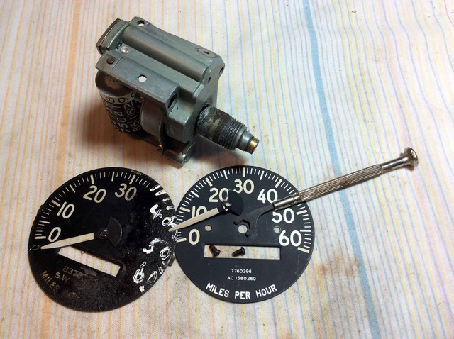
I removed the two speedo bezels by nibbling under the edge with a screw driver. There is a sweet spot to this process where the screw driver needs to be thin enough to bite under the bezel and strong enough to allow a twisting motion to lift the metal. Don't horse it. Clean results but the units are not good candidates.
I found a tool that works well for removing the needles without bending. Will add a pic later.
I intended to swap the good face onto the working speedo but the two faces are not a perfect match and the odometer numbers on the working unit are washed out. A smart purchase would solve this problem but I am conflicted over the various speedo choices.
_________________ Don Alvarez
Retired HS Teacher
Central Florida
M38 Project
Last edited by Naugha on Fri Feb 04, 2022 2:35 pm; edited 1 time in total
Nice. I will take a look see but evaluation of serviceability is my goal.
When it comes to repair, as the saying goes...
Only watch repair experts and darn fools will open up a Rolex.
Then there is the last comment from the control room at Chernobyl.
What could possibly go wrong??
Paying to have these things repaired sounds a little over the top unless you are in a factory resto project.
If a unit is really DOA, being a former Bio teacher, I know what to do. Anyone that is interested, I have a technique that can be used to remove the entire anterior portion of a frogs nervous system with no damage to the cranial nerves. The frog is still dead and no repairs are intended .... but how often do you get to see such fine anitomical details. _________________ Don Alvarez
Retired HS Teacher
Central Florida
M38 Project
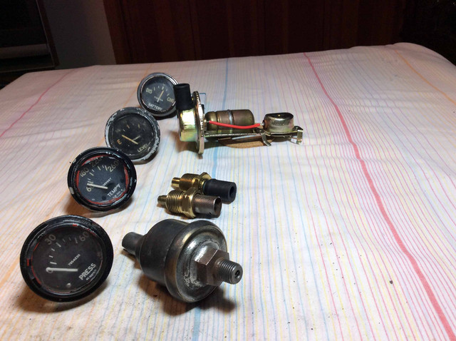
Posted: Tue Feb 01, 2022 12:03 pm Post subject: Fuel Level Gauge & Sender Test
Fuel Level Sending Unit - Expected resistance range readings from test chart.
30 ohms = Full
15 ohms = Half
0 ohms = Empty
My Fuel lever sender test results: 6 -36 ohms
So the fuel lever sender looks OK to me.
Fuel level gauge response with or without sender in line:
(25 v produced by two 12v battery jump packs in series.)
* No needle deflection from EMPTY unless you rotate the gauge so that gravity brings the needle slightly above the Empty mark, at which point the needle will then peg on FULL. Not a normal response I suppose.
* I guess both of my old take off fuel level gauges are defective.
I know the choices, but hearing again about the success stories of others would be helpful, unless gentilemen dont discuss their private fuel gauge choices in a public forum _________________ Don Alvarez
Retired HS Teacher
Central Florida
M38 Project
The needle moving when you tilt the gauges is normal, but has nothing to do with electrical operation. It is however a simple mechanical check to do before buying used gauges.
The fuel and oil pressure gauges have two coils inside. Power to the gauge is directed to both coils. One is grounded internal to the gauge. the other goes to the sending unit. With an ohm meter you should be able to check the value of both coils. You do need to put the ohm meter on the correct terminal where the power is fed to the gauge.
In operation applying power to the gauge with no sender attached, only the internally grounded coil is energized. This is the full scale coil. with just power on the correct terminal and ground on the case the gauge should indicate "full" or "60" pounds of pressure. Only when current starts to flow through the other coil to ground through the sending unit will the needle start to swing to the left. _________________ '52 Dodge M37, '42 GPW, '48 FrankenJeep CJ2A/M38, '50 CJV-35(U), '51 M38, '42 WC-57 Command Car, '44 WC-51 Weapons , (2) M1941 Sperry 60" Anti-Aircraft Searchlights, John Deere M-gator, '44 White M3A1 Scout Car
Only when current starts to flow through the other coil to ground through the sending unit will the needle start to swing to the left. mdainsd
So, I may not be done yet ?? Is it DOA or not??
I did try runs with the sender in the circuit (negative bat. wire attached to the body of the sender) but saw the same needle response (no movement unless case was tilted so needle was past EMPTY mark.... then FULL peg of needle.
The full scale coil is probably getting power/ grounded to the sender ??
But I need to go back and check that the other coil is grounded to the case ??
What do those two grounds physically look like?
Without the sender, shouldnt I be getting full needle deflection without any need to play around with the orientation of the gauge?
Thanks for your patience. _________________ Don Alvarez
Retired HS Teacher
Central Florida
M38 Project
The two grounds are the case of the gauge and the body of the sending unit.
Read my post again. Power on the gauge and ground on the gauge (no sending unit) should produce full scale deflection. You can check this coil with an ohm meter. one lead on the gauge case, one lead on the power input terminal on the gauge. If you get an open reading the gauge is kaput.
then check the other coil, one meter lead on each of the two terminals, nothing hooked to ground. If open, again kaput. _________________ '52 Dodge M37, '42 GPW, '48 FrankenJeep CJ2A/M38, '50 CJV-35(U), '51 M38, '42 WC-57 Command Car, '44 WC-51 Weapons , (2) M1941 Sperry 60" Anti-Aircraft Searchlights, John Deere M-gator, '44 White M3A1 Scout Car
Don you should not shop for new gages until you have determined the part numbers of the three senders and the part numbers of the three sender dependent gages. In most case senders are matched to a specific gage by part number. Keep in mind the many changes this M38 instrument system underwent. The first set of gauges uses external resistors with them and these gauges cannot be substituted with the later internal resistor gages unless you remove the external resistor from your system. Certain sender part numbers are restricted to use with certain part number gages. Then the sender's range must match the gage's range. _________________ Wes K
45 MB, 51 M38, 54 M37, 66 M101A1, 60 CJ5, 76 DJ5D, 47Bantam T3-C & 5? M100
Wes. My last pics show the inexpensive flea bay fuel sender I bought last year (Packard connector). The vendor ad used the fits M38 claim which I now understand may not always be the correct part. I also now know senders are usually paired with a particular model gauge and will try to match what I already have to what I may buy.
When I go to the Florida MVPA rally in March there will be a multimeter in my pocket along with some gauge testing notes and a list of M38 gauges from the era. If nothing original turns up in good shape then Repop City it is.
BTW.
I have the three dash lights with their red shot glass lenses. The guts are in good shape but rotten wires. I think even my limited skills can tackle this part of the dash rebuild. _________________ Don Alvarez
Retired HS Teacher
Central Florida
M38 Project
All times are GMT - 6 Hours Goto page Previous1, 2, 3Next
Page 2 of 3
You cannot post new topics in this forum You cannot reply to topics in this forum You cannot edit your posts in this forum You cannot delete your posts in this forum You cannot vote in polls in this forum