Now that was quite simple Ron. You described your circuit exactly like I described mine above it just using slight different wording.
But we got the primary side of the distributor and coil squared away and now we seem to be stumbling a bit on the description of the starter solenoid terminals.
First they fall into certain classes.
Continuous duty and intermittent duty.
You should be using an intermediate duty solenoid?
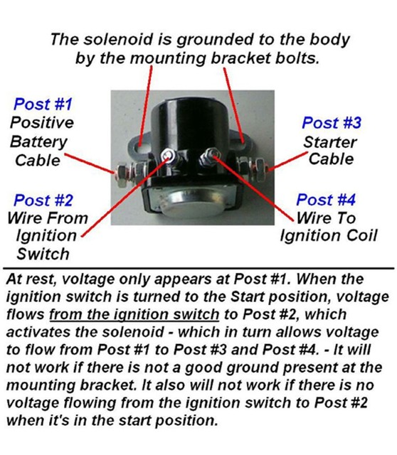
Now these solenoids are really just heavy duty relays. The BIG posts on each side are for the heavy juice from the battery and the heavy load to whatever is using the load.
These terminals are called BAT and Load.
Now here is where things can get a bit odd. There are two types on intermittent duty solenoids. Those with coil power terminals grounded internally (Single switch terminal) and those with coil terminals grounded externally (two small terminals) one marked Sw (Switch) and one marked Grd (Ground).
The Internally grounded, single small terminal solenoid operation. The ignition switch 12V output is delivered to the single terminal marked Switch. Then the 12V flows thru the small magnet coil and to an internal ground and the magnet is energized and closes the large contacts.
The Externally grounded, Dual small Terminal solenoid operation. The ignition switch 12V output is delivered to the small terminal marked Switch (SW). Then the 12V flows thru the magnet coil and out thru the other small terminal marked Ground (GRD) and to a vehicle ground thus energizing the coil magnet and closing the large contacts.
As you see they function the same but the grounding of the 12V in to the magnet coil happens two different places.
Now I think the solenoid you are describing is the Two small terminal externally grounded type.
What becomes very odd is how you wired your solenoid and how you named those terminals?
The starter solenoid I have has two primary coil terminals ("Ford style"?), one is connected to the "start" position of the ignition switch, and the other connected as described above to relay 12v into the coil primary.
Since the small magnet coil in the solenoid is the only coil in there most of us just call it the magnet coil. The terminals aren't primary?? but as I said above one is Switch and one is Ground. What you have done is route your start solenoid's magnet coil ground thru your ignition coil first then to ground. Yes your solenoid will still function but the loads imparted on it by the detour you took in it's ground wire will have some effect on the quality of the ground.
The industry standard with either type solenoid is to attach the hot 12V when cranking wire from the Switch terminal to the input side of the ignition coil. Remember the only time this solenoid Switch terminal is hot is when the ignition/start switch is in the start position.
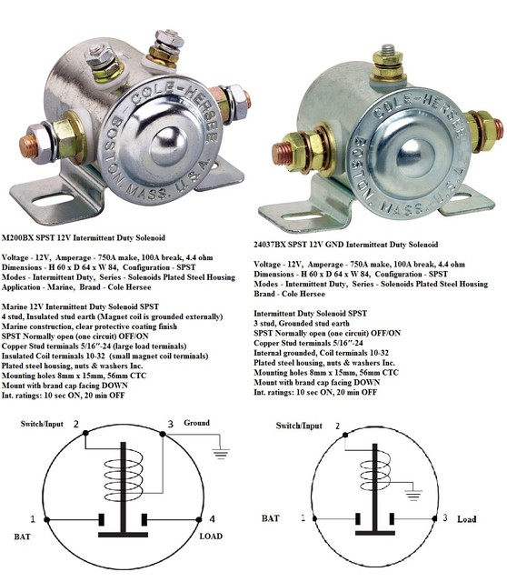
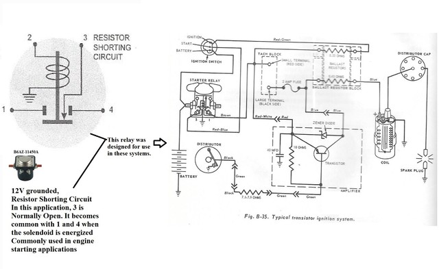
In this illustration no matter which of these two solenoids you have the ballast resister bypass wire to feed 12V direct to ignition coil while cranking would be attached to terminal #2.
I would advise you to transfer your straight 12V juice wire for your ignition coil to the switch terminal side (#2) of your solenoid and connect a dedicated single ground wire from the solenoid's magnet coil Ground terminal (#3) to a chassis ground.